Crossing the Threshold from Design to Manufacturing

In NX’s integrated CAM module, the software automatically identifies the geometric features suitable for machine.


Latest News
June 1, 2014
 In NX’s integrated CAM module, the software automatically identifies the geometric features suitable for machine.
About two years ago, Guy Nelson, who owns and operates Anvil Design & Manufacturing in Fargo, ND, picked up a CAD-CAM bundle: SolidWorks and SolidCAM. The deal was irresistible. He’s always planned to offer CAM-related services as part of his business, but the right opportunity never came along. This April, it came in the form of a client who wanted him to help produce a whammy bar, the sound effect-producing handle on an electric guitar.
“Once we started using the CAM package, we changed our design,” said Nelson. “Once we got into it, we realized that the area where we placed fillets apart, having a fillet somewhere, or the size of the fillet, affects production. So we went back to engineering.”
In crossing the threshold from design to manufacturing, Nelson is discovering the difference between simulated machining and real-world machining. “Without machining background, coming from just designing the part, we had to learn what the people on the shop floor are looking for,” he said. “Understanding the tool, knowing whether it might break, knowing how to hold the tool—those are areas we had to work our way through.”
The emergence of integrated CAM packages—programs that let you visualize machining operations from inside CAD—makes it easy for designers and engineers to understand how they might produce a part. In theory, CAM reduces unanticipated manufacturing glitches by preventing designers from introducing features and forms that are difficult—or, in the worst cases, impossible—to build.
But to delve into real-world machine, the CAM software operator must be willing to literally face the physical equipment. Michael Huggins, president of PCS engineering, cautioned, “You can learn a CAM package like you might a video game, but you really need to know what you’re doing with the tool.”
Derek Hart, Siemens PLM Software’s marketing manager, manufacturing engineering, noted, “Operating the CAM software is not difficult. But the interaction of the tool and the material is a difficult learning curve. There are so many ways it can go wrong—pockets that cannot be machined, a small change in the diameter of a feature that makes the valley impossible to cut, the way the chips must be ejected properly.”
Getting to Know the Machine
Nelson’s client is planning to manufacture the whammy bar with a Tormach-brand CNC machine. Anvil Design has been contracted to generate the G-code, used by computer-controlled machine to cut the part. This is new territory for Nelson and his colleagues, who feel much more at home in SolidWorks CAD than in SolidCAM.
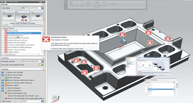 The DFM module automatically checks and identifies potential production problems based on CAD geometry.
“We did our research to understand the machine the client bought,” recalled Nelson. “We learned the coordinate direction, how it operates. We’re learning how to best make the part, how to setup fixtures, and how to build multiple parts at the same time.”
A standard feature of CAM systems is a library of industry-accepted machines that come preloaded with the software. The selectable list allows you to specify which machine you’d use to produce the part. When generating the tool path or the G-code, the software takes into account the specific machine’s tooling area, material holding method, the shape and length of its tool arm, and the way it cuts and drills. On complex parts, the choice of cutting direction, angle and speed—tooling strategy—determines the effectiveness of the job. Therefore, to be a good CAM programmer requires knowledge of the equipment itself.
“If we were to do it all over again, we would have been in contact with SolidCAM tech support a lot earlier,” reflected Nelson. Shaun Mymudes, COO of SolidCAM, would have welcomed Nelson’s outreach. “We have 30 people,” he said. “Out of those 30, we only have seven salespeople and three administrative. The rest—20 of them—are involved in some kind of support.”
For a SolidWorks user like Nelson, SolidCAM is “a natural extension,” said Mymudes. He added, “The ‘common platform’ approach drives a bidirectional information flow between the designers and the manufacturers … both can use CAM simulations to illustrate their suggestions and opinions.”
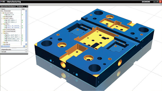
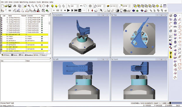 LSA Manufacturing uses DP Technology’s ESPRIT CAM software. The operation table shows there are more than 112 separate operations to machine this part. Some are created automatically; most are based on the programmer’s decision. Therefore, the programmer’s experience with the equipment plays an important role.
To make CNC programming easier, SolidCAM offers the iMachining feature, a patented wizard-based approach to generate tool paths and specify optimal feed and speed. Mymudes explained, “[The iMachining feature] completely controls chip thickness, making sure the tool load is perfectly optimized through the entire cut, ensuring the best possible tool life.”
A Good Programming Job
Todd Paul, president of Land Sea Air (LSA) manufacturing, observed, “You can machine a part 50 different ways. The end result might be the same, but one way by one guy might take one hour; another way with another guy may take 100 hours.”
Having worked with many CNC programmers, Todd can often spot telltale signs of inefficiency. “You look to see whether there are bad [machine] moves, whether the machine breaks tools because it’s moving too fast, whether the speeds and feeds are right or wrong,” he said.
About 80-90% of LSA’s clients are from the aerospace industry, which widely uses Dassault Systemes’ CATIA CAD program. Todd and his staff use ESPRIT CAM software from DP Technology. Todd’s CAM reseller is PCS Engineering, based in Timonium, MD. Its owner Michael Huggins once wrote CAM software manuals (at the time such manuals were still distributed in printed form). Huggins said, “In ESPRIT 2014, when you start a new file, it asks what machine you’d be using. Based on that input, the software sets all the machine parameters right away.”
The latest release, ESPRIT 2014, incorporates a cloud-hosted database to let the software recommend the best tool options. Based on uploaded information about the geometric features that needed to be produced (pockets, shoulders, slots, and so on), the software automatically creates a list of best-fit tooling options, ranking them in the hierarchical order.
On complex programming jobs, Todd doesn’t hesitate to call Huggins. “He [Huggins] uses Go To Assist [a remote desktop control program developed for tech support],” said Todd. “With it, he’s usually talking to me within 60 seconds. He can [virtually] take over my desktop to show me how to program a job correctly.”
“It’s pretty much impossible to make the first part right. Invariably, the programmer or the machinist might make a mistake,” noted Todd. “But with a good programmer, when the job is up and running, it can run as many as 1,000 parts and the last part is exactly the same as the first part.”
Longer Lifespan for Tools
Tools break. That’s the unavoidable part of real manufacturing where metals—not pixels—cut into each other. But according to Todd, something called Profit Milling, facilitated by ESPRIT CAM software, is defying the usual lifespan of cutting tools.
“We have a tool that we’re cutting materials with,” said Todd. “According to the tool manufacturer, its life is between 30-120 minutes. We’re getting 1,200 minutes with this tool. It’s strictly because of a tool cycle that ESPRIT calls Profit Milling.”
Daniel Parry, DP Technology’s application engineer, explained in a company-produced video that “Profit Milling is a 2-, 3-, 5-axis rough machining strategy … We have seen cycle time reduction along with five to 10 times the tool life compared to traditional pocket milling cycle.” The operation, Parry pointed out, is a tricordial motion characterized by “consistent cutting conditions” and “dynamic feed rate”—the machine adjusts itself to maintain constant chip load to keep the results consistent. This gives you the uniformity that spans from part No. 0001 to No. 1,000—what Todd views as one of the telltale signs of a good CNC programming job.
Spellcheck for Manufacturability
“CAM software are getting easier, but the physics of metal cutting is the learning curve,” observed Siemens’ Hart. “The real knowledge of manufacturability comes with experience. You have to break tools, make scraps to get it.”
Some of that knowledge can be encapsulated in the software itself. One product that fits the bill would be DFMPro from Geometric, a partner product of Siemens. Think of it as the equivalent of a spell checker for manufacturing operations. The company writes, “DFMPro assists design engineers in identifying features of a design which are difficult, expensive and impossible to manufacture, at the design stage itself. This helps in avoiding downstream issues which impact cost, quality and time to market. DFMPro covers various commonly used manufacturing processes like machining (milling, turning, drilling), injection molding, casting, sheet metal fabrication and assembly.”
DFMPro’s checklist extends beyond the simple act of production. It also considers whether your part, designed as it is, will permit easy disassembly for repair when it starts to show wear and tear. The company writes, “The rules take into account various Design for ‘X’ (DFX) issues which typically occur later in product lifecycle such as serviceability, assembly etc.”
CAD files routinely get passed over to CAM software operators and machine programmers, but the flow of knowledge from the opposite direction—CAM knowledge traveling upstream to designers using CAD—is currently not the norm. That knowledge flow—seeming going against the traditional current—may offer an opportunity to cut down unintended production hiccups.
Hart acknowledged, “Manufacturing is hard.” He added, “But that doesn’t meant people shouldn’t try to learn it.”
More Info
Subscribe to our FREE magazine, FREE email newsletters or both!
Latest News
About the Author
Kenneth Wong is Digital Engineering’s resident blogger and senior editor. Email him at kennethwong@digitaleng.news or share your thoughts on this article at digitaleng.news/facebook.
Follow DE